EMI Filtering for High-Reliability Applications
Amanda Ison
Electromagnetic interference (EMI), or electrical noise, is generated by everything from cellphones to solar flares and can make accurate signal transmission as difficult as trying to have a clear conversation in a noisy room. To improve signal clarity in electronic circuits, device designers turn to EMI suppression filters.
Effective EMI filtering is necessary for almost every modern electronic device, including devices that generate their own EMI, as well as devices that are sensitive to EMI within their environment, and is especially important in high-reliability applications that utilize lower-power signals and have strict signal fidelity demands. High-reliability EMI filters are designed to consistently meet or exceed performance requirements and are vitally important to any industry with a high cost of failure. For example, many medical, military, and defense applications depend on high-reliability filters for the accurate transmission and reception of signals required to ensure patient and soldier safety or achieve mission success. High-reliability filters also play a crucial role in a number of commercial applications, such as instrumentation, where sensitivity to low-power signals in a noisy environment is a requirement.
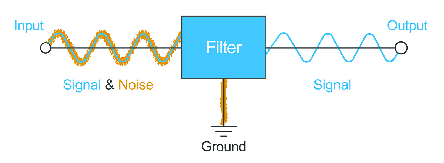
Figure 1: The basic concept of EMI filtering.
FILTERING PROPERTIES
The primary purpose of an EMI filter is to suppress the transmission of selected frequencies of a given signal. In most cases, a simple low-pass filter, which passes a low frequency signal while blocking out unwanted higher frequency noise, will be sufficient. The cutoff frequency is the frequency at which a filter begins to attenuate part of the signal, and is typically defined as the point at which the signal amplitude is 3 decibels (dB) below the nominal passband value. A filter’s capacitance and inductance values are carefully selected to achieve the desired cutoff frequency and frequency response.
Insertion loss values, which refer to the ratio of the strength of an inserted signal to the strength of the transmitted signal and are typically expressed in decibels, are a prime characteristic of filter efficacy. Ideal insertion loss for the frequency range of interest is 0dB and is infinite for all other frequencies. However, filters are complex devices that are subject to external influences including parasitic inductance, parasitic capacitance, component resonance, and circuit resonance that make ideal performance impossible. Once a filter has been designed and produced, users can analyze its insertion loss across a wide range of frequencies to get an accurate depiction of its performance envelope.
Other characteristics that affect filter efficacy include equivalent series resistance (ESR), dissipation factor (DF), and Q factor. Low ESR is an indication of a well-designed filter that will not dissipate much energy during its operation. Low DF, which takes into account both the ESR and reactance of the filtered capacitor, is another, as it its inverse: Q factor, which is also used to denote filter quality in some industries.
CIRCUIT SELECTION
There are several different circuit configurations utilized for EMI filtering, ranging from a single grounded capacitor to a circuit with up to three elements. Ideal selections depend on the unique characteristics and properties of the device the filter will be employed in, such as device impedance.
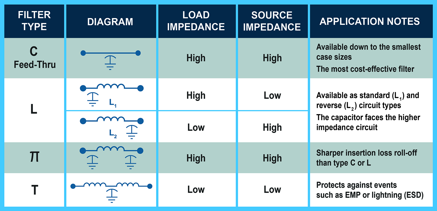
Table 1: EMI filter circuit selection options.
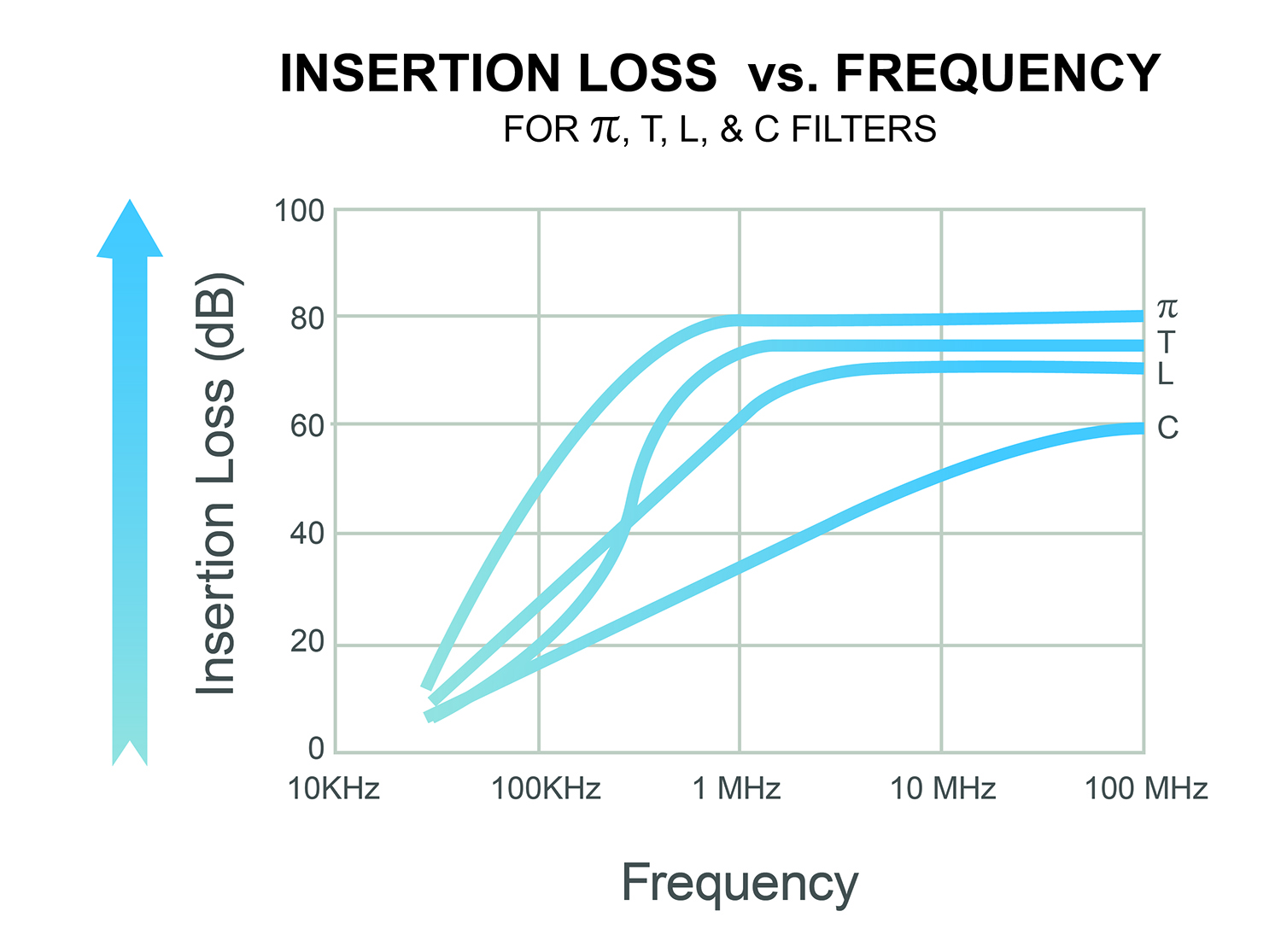
Figure 2: Insertion loss vs. frequency for multiple filter configurations with a full load in a balanced 50Ω
system that accounts for component and circuit resonances.
VOLTAGE RATINGS
EMI filter performance must be matched to capacitor performance for effective filtering. Ceramic capacitors, which use very thin layers of ceramic dielectric to separate conductive layers from one another and prevent the free flow of electricity, can be designed to withstand voltages in excess of 1,600VDC. So, filter designers must choose the appropriate dielectric materials and dimensions best suited for each capacitor’s unique set of performance requirements.
Filters must also be designed and tested for each circuit’s AC or DC voltage conditions. DC filter ratings are not the same as AC filter ratings, so a filter’s ability to successfully withstand high DC voltage does not necessarily predict its performance when exposed to high AC voltage and vice versa. For instance, AC-rated filters will often have lower capacitance values to prevent overheating and damage resulting from reactive current heating, while DC-rated filters expected to experience short, irregular bursts of voltage, like those employed in implantable cardiac defibrillators, are likely to undergo a pulsed voltage test to ensure capacitor integrity.
In addition to being able to withstand the appropriate voltages, well-designed filters also resist the leakage of current across the capacitor. It is impossible to construct a capacitor that completely prevents this flow of electricity, but filter designers can mitigate leakage current through proper material selection to minimize its impact on device performance.
MULTIPLE FILTERED LINES
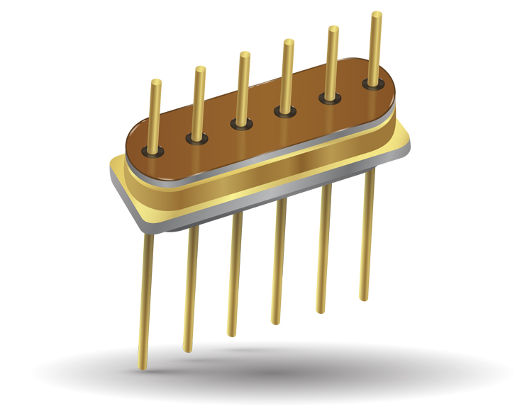
Complex electronic devices often require filtering on multiple signal or power lines. One way to isolate them from one another is to use a specialized metal ferrule that contains and acts as a common ground for multiple filters, connecting their cases together while the pins remain isolated.
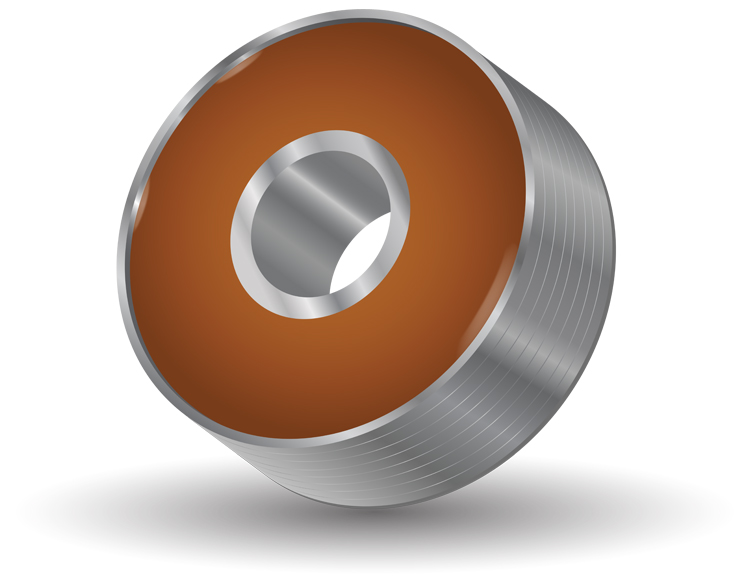
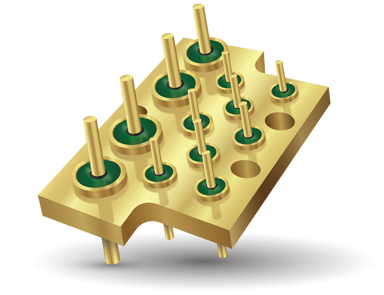
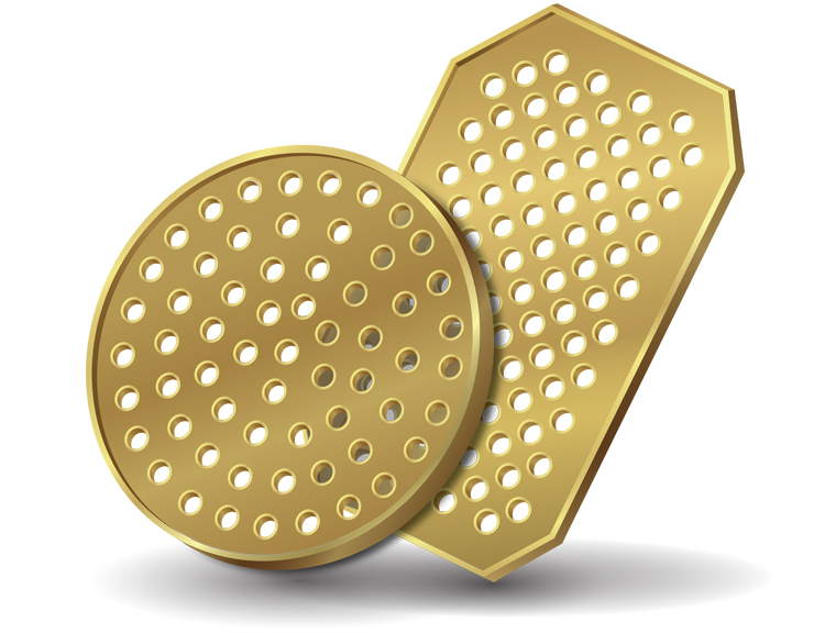
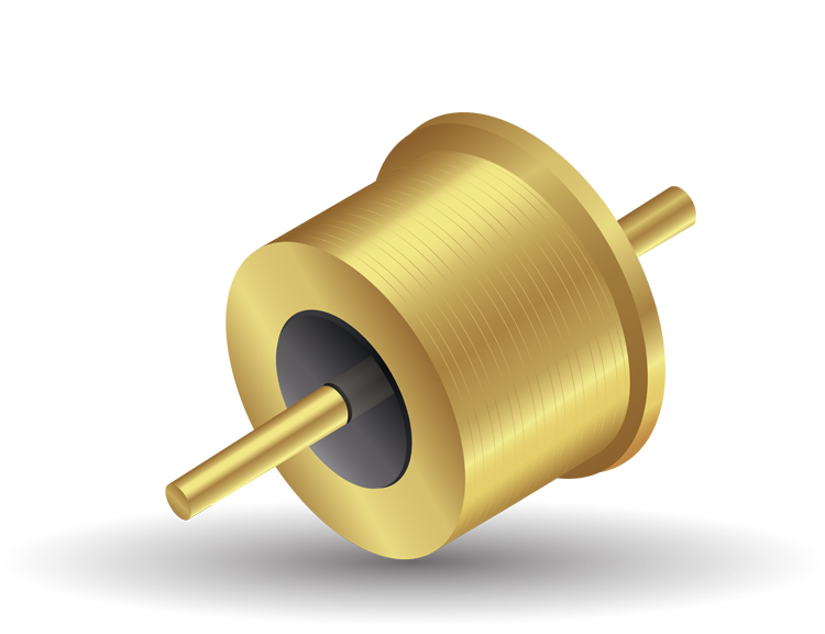
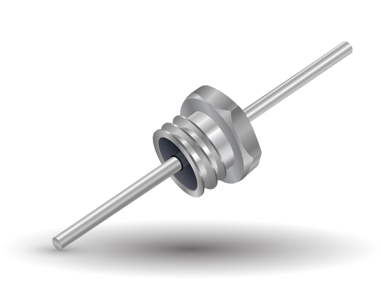
A single EMI feedthrough filter is typically constructed as a donut-shaped capacitor called a discoidal, the inside and outside diameters of which act as connection points for the case and the lead and serve as the poles of the capacitor. In applications where space is at a premium, multiple discoidal capacitors can be integrated into a single piece of ceramic referred to as a capacitor array and installed in a feedthrough for device integration. These types of filtered feedthrough assemblies provide the highest concentration of filters in the smallest physical volume and are often used in implantable medical devices, in which high density and minimal volume offer a real competitive advantage, as well as for commercial and military connector filtering.
Experienced filter manufacturers can also develop fully tested and assembled feedthrough and capacitor arrays in custom shapes and sizes to facilitate seamless, single-step integration into more challenging device designs to reduce the possibility of component damage or installation errors. There is no hard limit on the number of capacitors that can be integrated into an array, but cost increases with quantity.
SYSTEM INTEGRATION AND INSTALLATION
A variety of case sizes and lead lengths are available to suit specific applications. For instance, miniature filters are available for applications with space and weight restrictions, and custom designs are available when existing case sizes are not an ideal fit. Some systems also require filters to exhibit rugged resistance against moisture and other contaminants, to employ airtight seals that prevent the leakage of gasses, or to account for environmental variables like the normal reduction in insulation resistance that occurs as ceramic heats up. Thoughtful materials selections and installation methods can achieve these characteristics and help prevent performance degradation over the component’s lifetime.
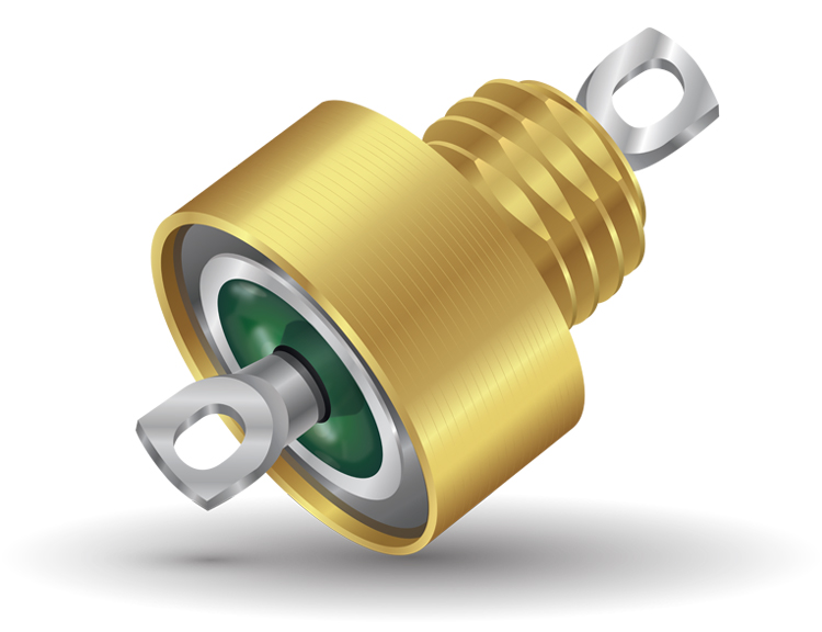
Although filters must be installed in an EMI shield, such as a well-grounded conductive enclosure, for optimal performance, device designers can choose from a variety of installation options. Solder-ins are one of the most compact options, are designed to withstand the heat of being soldered into a final assembly, and can also provide excellent levels of hermeticity. Other options include bolt-style filters, which are threaded and may have a hexagonal head; cylindrical filters, which have the largest internal volume and can accommodate complex circuits in a single package, such as a Pi or T filter; and screw-style filters. All filter styles have the option for hermetic sealing on both ends of the component to prevent outgassing.
Additional measures can be taken to protect the integrity of the filter both during and after installation as well. For example, preheating a solder joint before exposing it to the full soldering temperature can avoid the application of unnecessary thermal stress, and gently handling filter cases can help prevent mechanical deformation.
TESTING AND INSPECTION
When filter performance is mission critical, filter selection should be limited to those that have been 100% tested for relevant properties. Standard high-reliability parts undergo electrical and visual inspections and additional testing sequences to further ensure filter reliability. There are also several US-MIL standards that provide extremely specific requirements for electrical, mechanical, and thermal testing procedures and results. Since most ceramics have a high propensity for crack propagation, ceramic components with any hint of mechanical instability will generally fail early on. Stress-testing high-reliability filters and capacitors eliminates any inferior parts that may cause trouble in the future.
AVX Corporation offers several different levels of testing to provide the required reliability for numerous applications. R-level testing is more stringent than standard commercial testing and includes a variety of tests designed to simulate filter performance under stress. B-class and S-class testing include more comprehensive tests than R-level, such as a radiographic inspection — a process in which a part is imaged with X-rays in order to non-destructively examine its internal structure. Group A and Group B refer to different test levels within a lot. Group A testing is performed on all lots produced, and includes some tests that are performed on 100% of parts and others that are only performed on a sample. Group B testing is generally performed on a sample and includes extensive life testing. Space-level parts, or S-class parts with Group B testing, represent one of the highest reliability levels achievable for an EMI Filter.
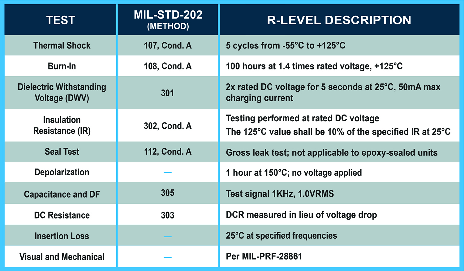
Table 2: AVX’s R-level testing procedures subject 100% of parts to these tests in the order shown.
Summary data for R-level screening is shared with customers and verification is included with product shipments.
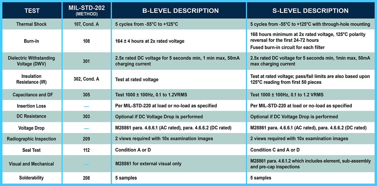
Table 3: AVX’s Group A testing sequence for MIL-PRF-28861 certification. These tests are performed on
a 100% basis when customers specify Class S or Class B reliability.
Actual testing sequences may vary slightly depending on the filter manufacturer and any special device requirements, but often include tests outlined in MIL-PRF-28861, MIL-PRF-31033, MIL-STD-202, MIL-STD-220, and other specifications. Experienced filter manufacturers will identify and execute the best testing regimens for each application.
COST AND MANUFACTURING CONSIDERATIONS
Filter specifications including circuit complexity, voltage and current ratings, size, and temperature resistance, as well as the desired reliability level and amount of testing required to achieve it, all impact filter cost to varying degrees. While many of these factors are governed by device-level requirements, there are some aspects of filter design in which experienced manufacturers may be able to reduce costs without notably affecting filter function. Any cost/performance tradeoffs should be thoroughly discussed during the design phase to ensure that a quality product can be created at a reasonable cost.
Proper material selection is an important element of cost because prices and functionality can vary significantly between different material options. For example, the usage of palladium rather than platinum for leads or capacitor terminations can result in significant material cost savings, but may make installation more difficult. Certain lead configurations and array densities can also drive costs up. In order to make the best selections, it is important to consider capacitor dimensions, such as thickness and shape, and to have a good understanding of the assembly process environment. Variables including whether the leads will be soldered, welded, or otherwise inserted into the final device can affect material selection due to the fact that certain material options are best suited for specific attachment methods. In some cases, device designers may also have insights that filter designers may not, such as the potential for greater cost savings via simplified or optimized installation that would make a costlier, more complex filter design worthwhile.
Figure 5: A cross-section of a medical filtered feedthrough with the capacitor, leads, and active and
ground joints indicated with arrows.
Additionally, seemingly minor changes to capacitor designs can have hugely adverse effects on the manufacturing and device design processes. For example, small changes in capacitance can sometimes require complete capacitor redesigns. While many devices have unique requirements that demand completely custom filters, some new devices can utilize an existing template to achieve shorter lead times and lower qualification and per-piece part costs for initial volumes.
COMMERCIAL FILTERS
Regulations for commercial filters and devices can vary based on the country in which they are sold. For example, some countries restrict the concentration of hazardous materials in electronics and may demand that manufacturers comply with RoHS or similar standards. Experienced filter designers are well versed in these requirements and can discuss various options, such as the usage of conductive polyimide instead of solder and cadmium-free terminations, with their customers.
Rules and regulations regarding the emission of electromagnetic radiation can drive the decision to use a filter as well. In addition to keeping harmful EMI out of a device, filters can also prevent EMI from escaping and interfering with other sensitive equipment in the vicinity. Almost every country has regulations that determine the approved type and amount of EMI that devices may generate.
![]() Accreditations, such as ISO 9001 registration, can help ensure that suppliers follow ethical manufacturing practices. In addition to these types of quality standards, many countries and companies also have regulations regarding the ethical selection of suppliers. Ethical filter suppliers comply with all labor regulations in their country of operation, as well as with larger international regulations, such as the Modern Slavery Act of 2015, SA8000, the EICC Code of Conduct, and ILO 18000.
Accreditations, such as ISO 9001 registration, can help ensure that suppliers follow ethical manufacturing practices. In addition to these types of quality standards, many countries and companies also have regulations regarding the ethical selection of suppliers. Ethical filter suppliers comply with all labor regulations in their country of operation, as well as with larger international regulations, such as the Modern Slavery Act of 2015, SA8000, the EICC Code of Conduct, and ILO 18000.
AEROSPACE AND DEFENSE FILTERS
 Manufacturing products for aerospace and defense companies requires compliance with strict rules and regulations that govern almost every aspect of device performance, manufacturing, and testing. Defense companies must often follow strict regulations regarding how they select and audit their suppliers. There may have a specific list of suppliers that have received accreditation to certain US military standards and/or other countries’ requirements that must be met in order to sell parts there. For example, the United States requires that companies comply with applicable export compliance regulations, such as Export Administration Regulations (EAR) and International Traffic in Arms Regulations (ITAR). Aerospace and defense suppliers must also follow certain regulations regarding the security and confidentiality of the products they are manufacturing, as well as any information regarding the product’s intended use or user. AVX is included on the Qualified Products List (QPL) for the Defense Supply Center Columbus, which is a part of the US Department of Defense.
MEDICAL DEVICE FILTERS
Medical device technology has advanced at an astounding pace in recent years, with devices becoming ever more compact, complex, and, in some cases, even less intrusive for patients. Due to the increasingly connected world we live in, these and other sensitive devices are subjected to growing levels of electromagnetic interference from our environment. Any unfiltered medical device is at risk for harmful interference from various sources of EMI. To maintain high levels of precision and reliability, many medical devices employ the use of EMI filters to minimize noise and maintain signal fidelity. Medical device filters often have some of the most stringent spatial requirements, and thus commonly use filtered feedthrough arrays or miniature discoidal capacitors, which deliver high-density performance in low-volume packaging.
Since a large majority of implantable medical devices are battery powered, it is important to minimize filters’ power to prolong device life. Measuring and minimizing equivalent series resistance (ESR) or dissipation factor (DF) can help keep unnecessary battery drain to a minimum, and high insulation resistance (IR) can help minimize current leakage across the capacitor. Modern implantable medical devices typically use primary cell, non-rechargeable batteries that are designed to last 10 or more years. However, since high-reliability implant battery technology has not kept pace with the miniaturization of many other electronics employed in these devices, minimizing power consumption is crucial to achieving target battery and device life expectancies.
 Early pacemakers and other implantable devices were not compatible with magnetic resonance imaging scans (MRI) due to the impact that such large amounts of EMI would have on device function. Fortunately, many implantable devices have since improved to the point that they can safely withstand certain levels of MRI exposure. The methods by which medical device designers ensure their devices are MRI-compatible and how they are tested can be proprietary to each company, but always requires various types of filters. As such, filter manufacturers supplying to the medical device industry must carefully consider the ways in which these testing procedures and subsequent MRI exposure may affect lead attachment methods, the usage of internal or external grounding, and other characteristics.
In addition to requirements for greater functionality, several global regulatory bodies also impose strict regulations, ranging from design to audits to documentation, on medical device manufacturers and their suppliers in an attempt to further ensure patient safety. As such, it is critical that medical device designers select filter manufacturers with a proven track record of compliance with regulations and reliable products. Medical device designers can also benefit from utilizing existing filter designs where possible, as doing so can result in qualification time and cost savings for implantable devices.
Optimal filter design is necessarily a collaborative process. EMI filters have a huge impact on, and are similarly impacted by, the design of the devices they are designed into. There are no one-size-fits-all solutions. Most filters are either customized or completely custom designed for a specific application, as even minor alterations to a filter’s electrical requirements, such as a slight increase in working voltage, can have potentially catastrophic consequences if the filter is not suitably modified to meet the new specification. Consequently, it is vital for device designers and EMI filter designers to work together and communicate clearly about the requirements and limitations for each and every aspect of each new design. Factors including capacitance, voltage rating, dimensions, hermeticity, and cost must be carefully balanced to arrive at an optimal end result as well.
In general, the challenging requirements of high-reliability electronic devices, and especially those employed in the demanding aerospace, medical, defense markets, have led to a need for increasingly complex EMI filtering. Through detailed discussions of the design considerations presented in this article, and careful consideration of the performance requirements unique to each individual device, device designers and EMI filter designers can work together to achieve the highest possible reliability levels.